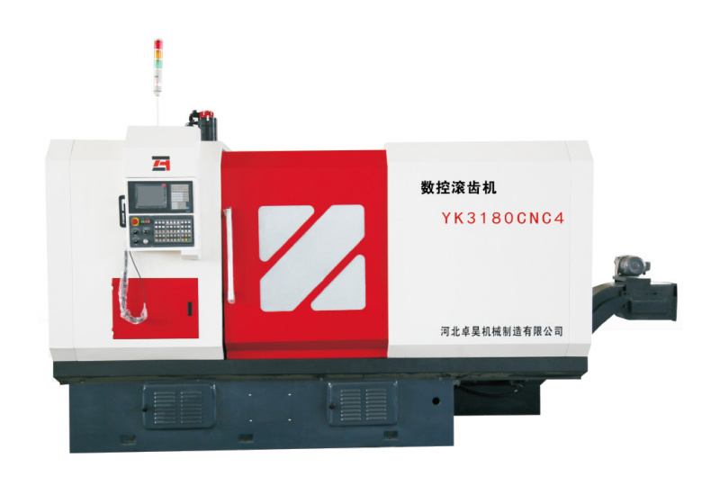
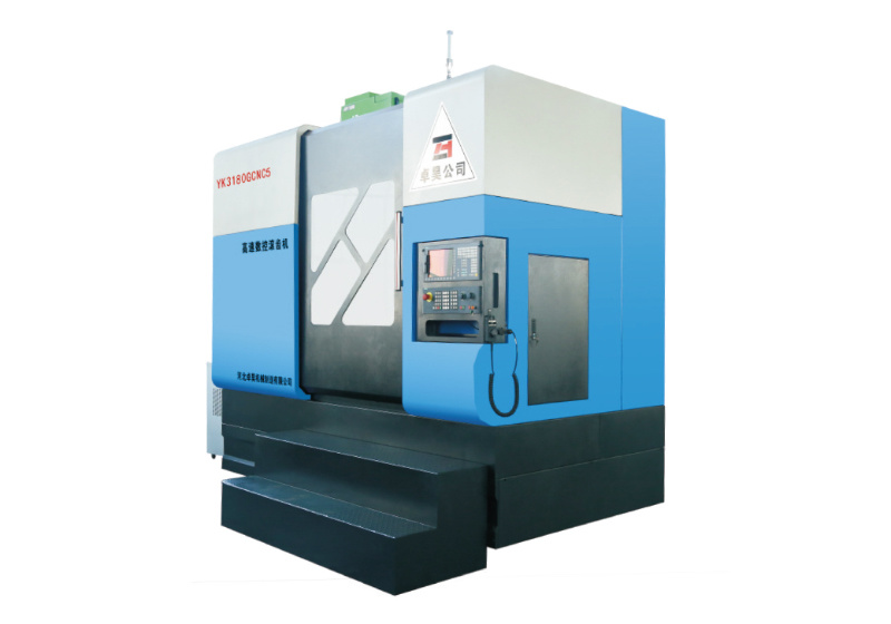
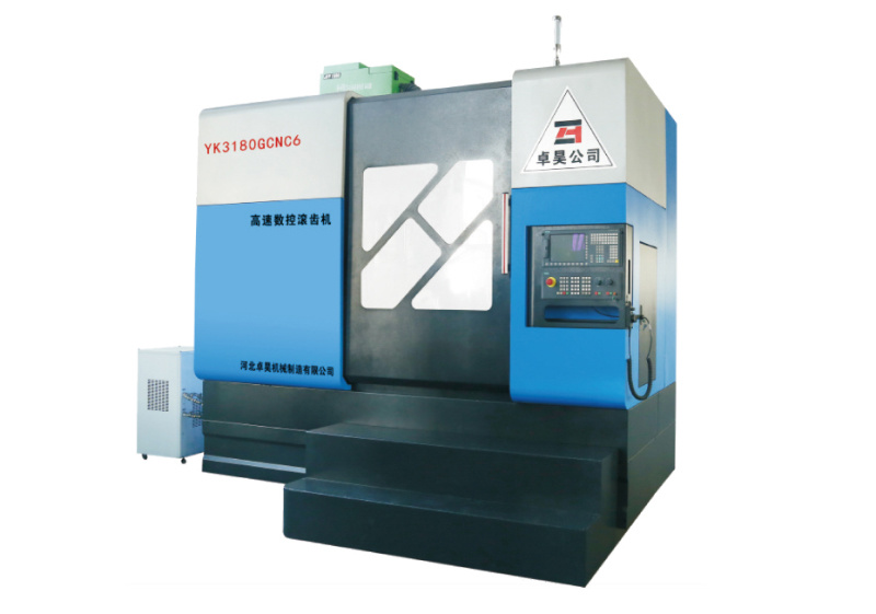
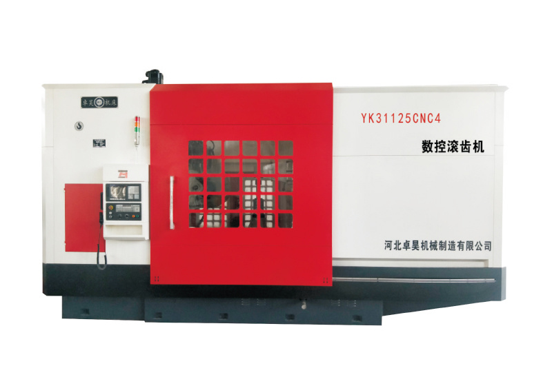
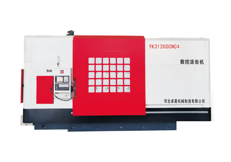
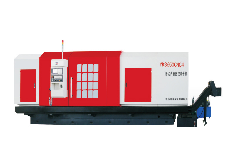
Adjustment steps of CNC gear hobbing machine
2020-11-01
Adjustment steps of CNC gear hobbing machine:
1. Before debugging, please pay attention to check the parts related to processing: such as toolbar, tool boss, mandrel, whether the positioning end face runout of the tool meets the processing requirements, and whether the fitting clearance of the workpiece is reasonable. Specific requirements:
1) The end face of the clamp rebounds between 0.006 and 0.013 (according to the size of the end face);
2) The radial runout of the spindle is less than 0.01, and the runout of the upper and lower center cones is less than 0.01; 3) The end face and radial runout of the hob shank is less than 0.01, and the radial runout of the hob pillow is less than 0.01;
2. Regardless of whether the intersection angle of the tool holder and the tool axis is installed, the product needs to be processed at a ±λ angle at the appropriate position (subtraction in the same direction and addition in the opposite direction, such as subtraction 3. Use product parameters Make calculations to correctly install and lock the speed change gear, differential speed change gear and cutter speed change gear.
3. Before starting, check the hob again, whether the workpiece is firmly locked and whether the hob is in a safe position.
4. After turning on the machine, make sure to lock the hob axial (up and down) initial feed (safety) position stop.
5. Manual radial feed, when the hob contacts the outer diameter of the workpiece (allowed to grab 0.1 for easy observation), the position at this time is the starting point of the effective feed position, and based on this, the first trial cutting is performed according to The following formula is used: when α = (17.5º~22.5º), the feed amount is: L = Mn×2. After completing a processing stroke, measure the tooth thickness (normal), and the required difference ΔSn×1.5 is The processing feed rate is the number of tools until a qualified tooth thickness is processed, and then the tool position is the final processing position. The feed amount of the sprocket is 1mm starting from the tooth depth minus the 1mm directly cut. When the tooth root in the machined position can be tested, the feed will be tested after testing until the final dimensions are determined.
6. Fix the position of the tool post-processing travel stop (travel switch) and perform cycle processing.
7. Use of hob: The tooth shape of the side teeth of the hob is incomplete, so it is not allowed to be used during processing. At the beginning of processing, the hob should start from the first tooth except the side teeth, and then gradually move to the other end. , until the tooth on the other side. When the tooth surface of the product is bitten, the knife should be moved in time when tightening the knife to avoid serious batches of unqualified products.
8. During the processing, you should always pay attention to the operating status of the machine, check the product in time, and correct problems in a timely manner.
Contact Us
Service Phone:
+86-13630891203, +86-13930960916
E-mail:
554590975@qq.com
Address:
No.16, Xingwan Industrial Zone, Ren County, Xingtai City, Hebei Province

